Prototype board
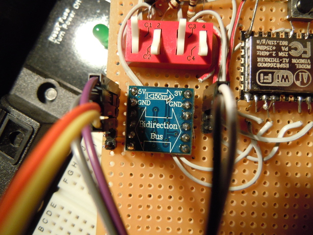
I made a prototype board, with a level-converter integrated, and some switches to change the programming modes.
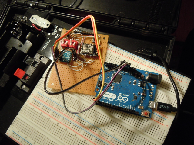
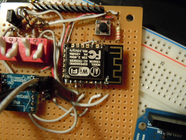
Soldering the ESP itself is not fun, I used resistor legs, they fit exactly in the holes. The arduino is here to provide the serial connection, and the 3.3V/5V.
Mode | GPIO15 | GPIO0 | GPIO2 Flash (running code) | 0 | 1 | 1 ROM (for uploading code) | 0 | 0 | 1
GPIO2 on my module is connected to a blue LED, this led should be off except when data is coming.
Communication
To test the communication, I used this code (for the Leonardo, will likely not work like that on other boards).
void setup() {

  Serial.begin(115200);
  Serial1.begin(115200);
}

void loop() {
  while (Serial.available()) {
    Serial1.write(Serial.read());
  }
  delay(50);
    while (Serial1.available()) {
    Serial.write(Serial1.read());
  }
}
The default Firmware spits its welcome/debug message at a baudrate of 76923… Don’t ask why, at least you know you can read it now. That’s especially useful when you will need to push a firmware and be sure your prototype card is ok.
Testing the RFID systems
I bought two kind of RFID, one for the Mifare (MFRC522), one for the 125kHz tags (RDM6300).
MFRC522
This one is pretty easy to connect.
| MFRC522 | ESP8266 |
|---|---|
| RST | GPIO5 |
| SDA(SS) | GPIO16 |
| MOSI | GPIO13 |
| MISO | GPIO12 |
| SCK | GPIO14 |
You don’t really need the RST (put to GND) and SS (put to 3.3V) if you only have one module.
I then used this code (https://github.com/Jorgen-VikingGod/ESP8266-MFRC522), changing the RST and SS pins (because the 15 and 2 are already taken on my board). And it runs directly using the Arduino SDK.
(You have to add the https://github.com/miguelbalboa/rfid library to your Arduino software)
I was able to scan some tags that were given with the module and Chicago’s ventra cards (just tested the ID for these), but I know you can overwrite some bytes that are not protected on the card. They use the ID of the card and maybe more, so don’t dream, you’ll likely not have free rides!
If you are curious about what the inside of such a card looks like. I guess the circle on the top right is a capacitor, the chip is the little black dot. No there is no magic pins here.
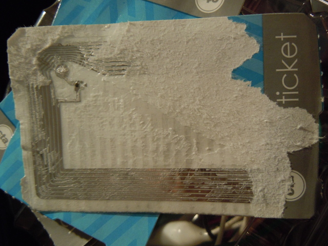
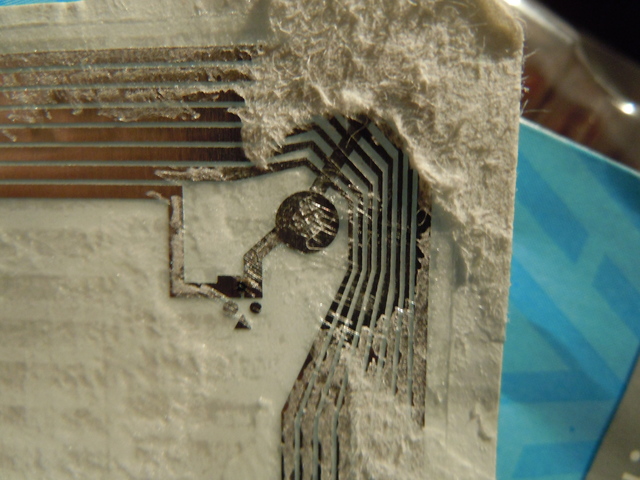
But yay, free tags everywhere on the street. And they are flexible and relatively moisture resistant, I didn’t ask for that much for so little!
RDM6300
This one is 5V based. So I had to use a level adapter.
Connexion is easier, and the code too. The module spits at 9600 bauds.
The code is sent with the following format:
0x02 |
I then used this bit of code to test it:
// Using the ESP8266 to communicate with the RDM6300 module

// Just connect (with a levelconverter!) the RDM6300 TX to the ESP RX

#include <ESP8266WiFi.h>
#include <SPI.h>

int  val = 0;
char code[10];
int bytesread = 0;

void setup() {
  Serial.begin(9600);    // Initialize serial communications
  delay(250);
  Serial.println(F("Ready!"));
}

void loop() {
  // Part of that is coming from
  // http://playground.arduino.cc/Learning/PRFID
    if(Serial.available() > 0) {          // if data available from reader
    if((val = Serial.read()) == 2) {   // check for header
      bytesread = 0;
      while(bytesread<10) {              // read 10 digit code
        if( Serial.available() > 0) {
          val = Serial.read();
          if((val == 2)||(val == 3)) { // if header or stop bytes before the 10 digit reading
            break;                       // stop reading
          }
          code[bytesread] = val;         // add the digit
          bytesread++;                   // ready to read next digit
        }
      }
      if(bytesread == 10) {              // if 10 digit read is complete
        Serial.print("TAG code is: ");   // possibly a good TAG
        Serial.println(code);            // print the TAG code
      }
      bytesread = 0;
    }
  }
}
I use a FTDI to connect my computer to the ESP now. My levelconverter provides 3.3V (more 2.8-3 than 3.3, but it works) so I don’t need another regulator. Connecting the RDM6300 to the TX of the FTDI and at the same time as the level converter going to the RX of the ESP, works. You can still push code, and read tags. I didn’t try, but it is probably a bad idea to scan a tag during upload with this configuration.