DINOctopus
If you are looking for the configurator, it is here: SysEx Configurator
What is it
DINOctopus is a small device made to merge/split/mix MIDI signals and act as a USB card as well.
Structure
This is a general diagram of when the device has 10 physical ports (5 in and 5 out). All the physical ports can be routed to any other port.
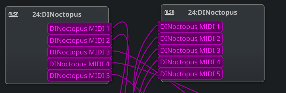
The USB ports are virtual and will through a single cable be displayed as multiple ports in your operating system:
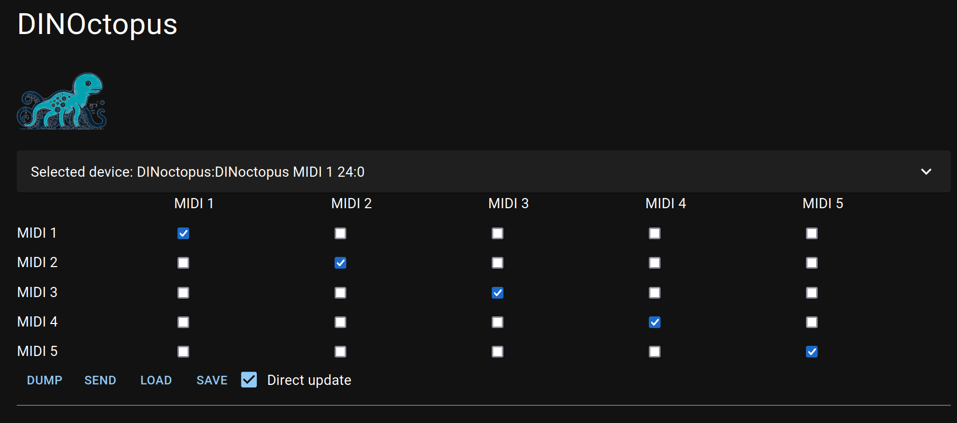
Configuration
The configuration is done using SysEX, there is a WebMidi implementation here: SysEx Configurator
Open Source Hardware and Software
Software
The firmware is available here: https://www.github.com/bjonnh/dinoctopus
There are builds of the UF2 files that can be directly sent to a RP2040 board by USB. Plug it while pressing the BOOTSEL button, and it will appear as a USB drive, just copy the file to it.
Latest release is always available at: https://github.com/bjonnh/dinoctopus/releases/latest
SysEX messages
This is the structure of the messages:
F0 44 49 4E 4F 00 <command> [optional_data] F7
Where
44 49 4E 4F  : Identifier of the device (DINO)
00            : Device number (0)
F0 and F7 are the normal sysex delimiters
and the replies:
F0 44 49 4E 4F 00 66 <response> F7
The commands are:
| Command | Description | Data |
|---|---|---|
| 0x00 | Identity (Not implemented) | |
| 0x01 | Dump the matrix | None |
| 0x02 | Set the matrix | 100 uint32/7 numbers (see below the format) |
| 0x03 | Get the matrix element at i,j | 2 uint8 between 0 and 5 for the input and output |
| 0x04 | Set the matrix element at i,j | 3 uint8 between 0 and 5 for the input, output and value as uint32/7 |
| 0x05 | Save in the EEPROM | None |
| 0x06 | Load from the EEPROM | None |
| 0x07 | Reset everything to 0 | None |
All commands will return either : 0x60 (ACK) or 0x61 (NACK) except for 0x01 and 0x03 that are special.
Technically there is no EEPROM on the RP2040, but I use the flash for that. It is not supposed to be written too often but that’s unlikely to be a problem for this project.
Any command that do not match the above will just be forwared to the port(s).
Dump the matrix (0x01)
This returns 100 uint32/7 numbers. You can safely convert them to uint32.
Get the element (0x03)
This returns one uint32/7 number that can be safely converted to uint32.
What is uint32/7:
Currently the values are stored internaly as an uint32_t, and we only use 0 and 1. The other bits will be used for filtering and other features. I call the type uint32/7 because SysEX only allow to send 7 bits per element, so we end up with truncated values. They are LSB.
So 1 is : 1 0 0 0
250 cannot be represented
But 256 can: 0 1 0 0
Etc.
I will probably send the sysex differently at some point or just ignore that 1 bit, we will see when we get there.
Hardware
Schematics and PCBs are available at: https://www.github.com/bjonnh/dinoctopus/tree/main/hardware/electronics
There are some more explanations of the interfacing on the Minitopus page.
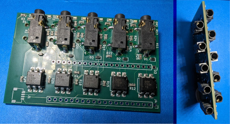
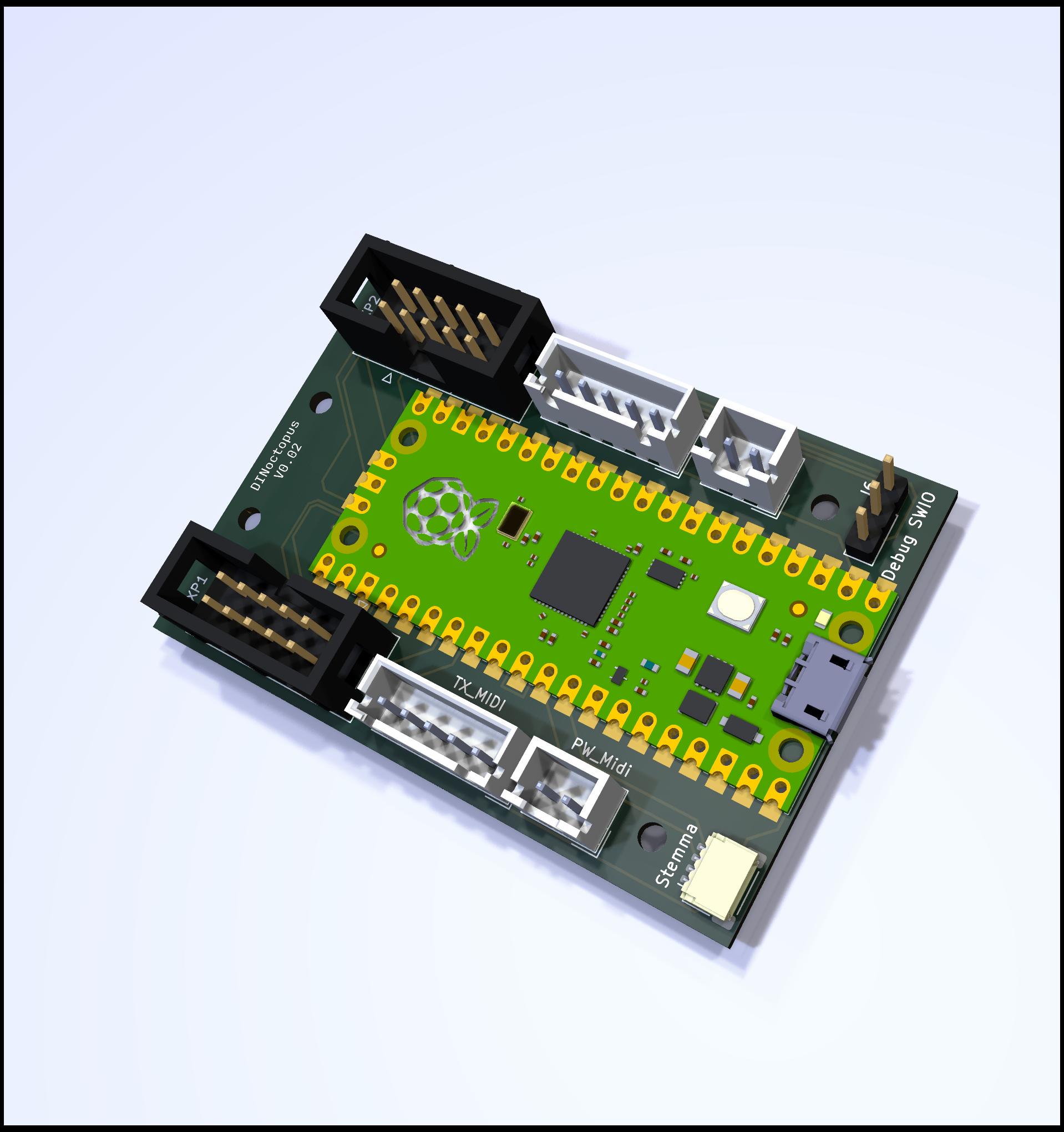
Current version (Revision 2)
A single board version, on which you just have to add a Raspberry Pico (or connect your own board at the right place)
As I figure some of you may want to use a different board, here are the pinouts:

Looking at the board, top of this schematic is the J3/J4 side on the picture of the board
History
Document
- 2024-06-01 Update for revision 2 and add all the documentation. This becomes the official documentation
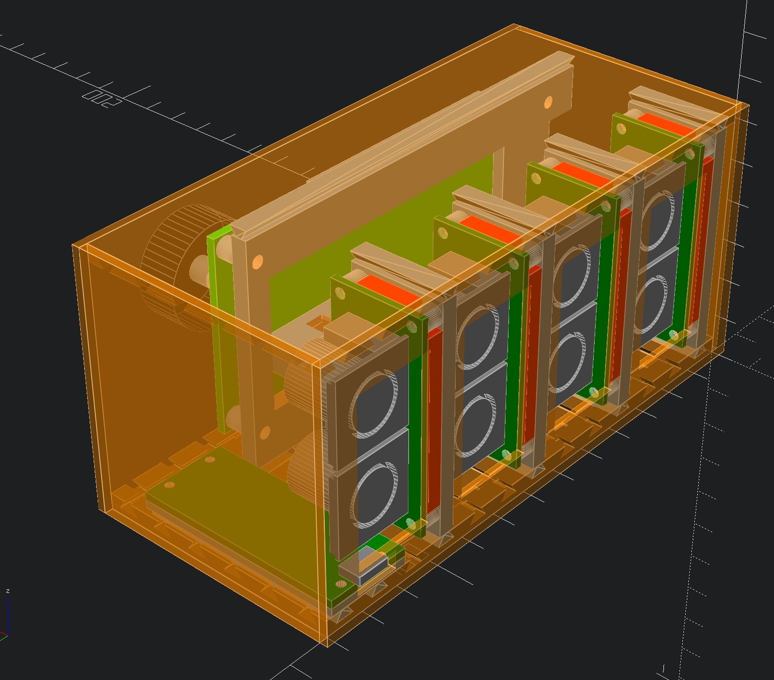
Revision 1
This version had a display with a rotary encoder to configure it.
It was made with several boards, one RX board, one TX board and one main board. The main board had issues, I used the wrong pinouts for the level converter of the display.
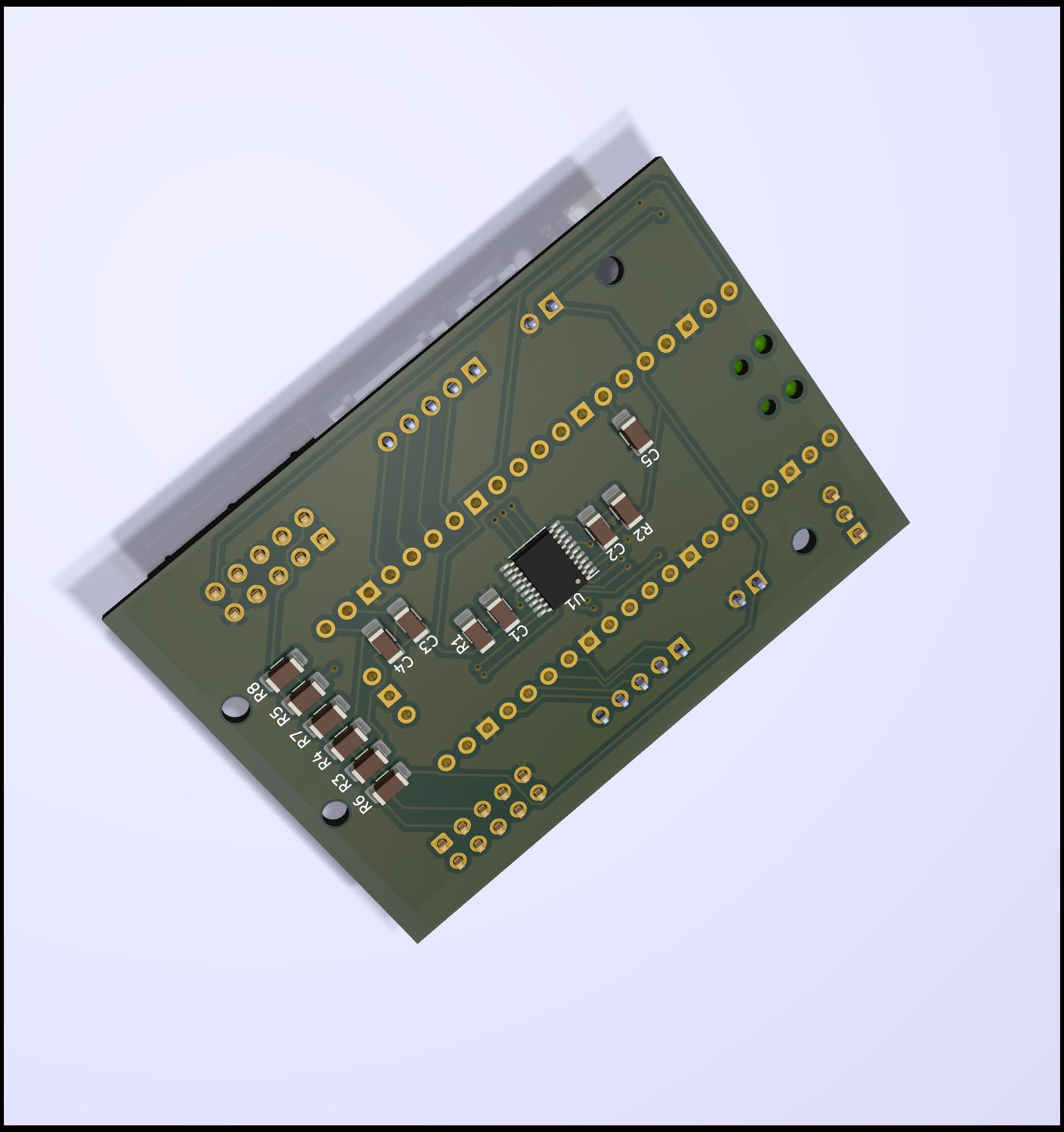
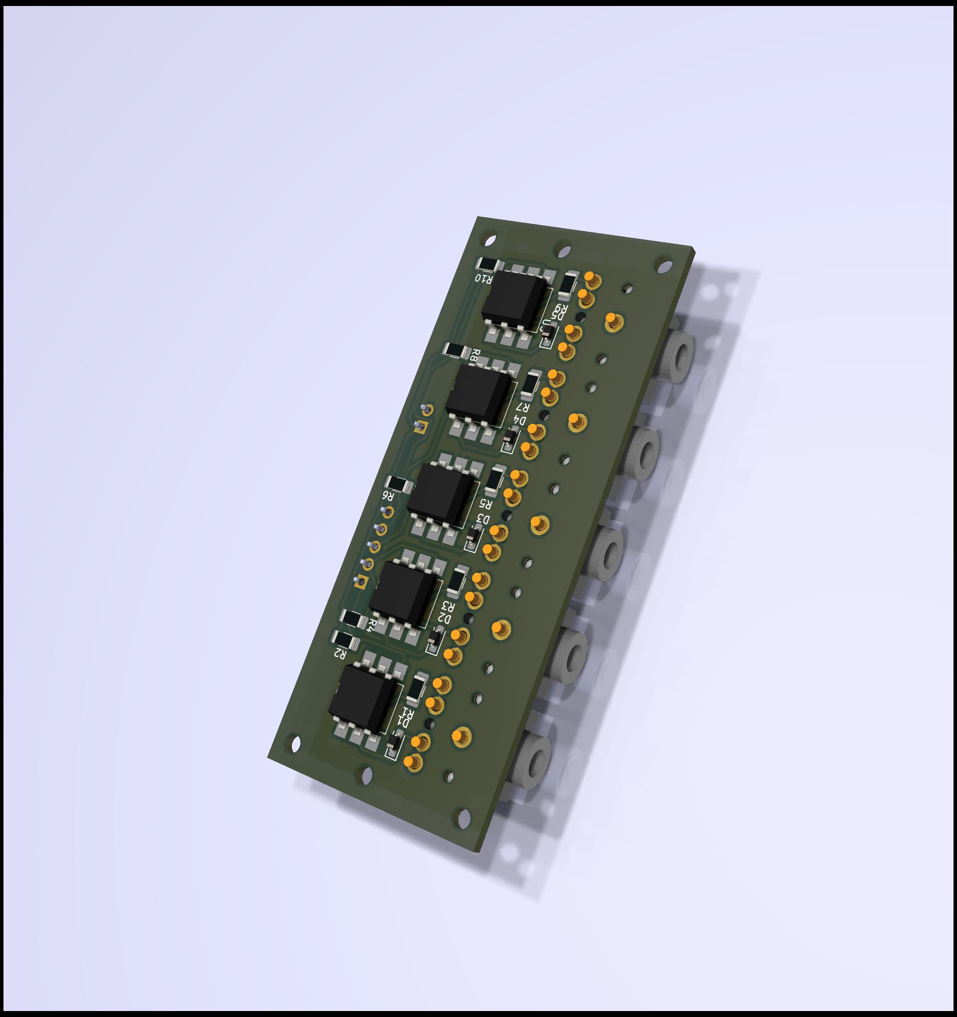

It was looking like that:
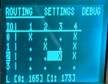
It used a repurposed cheap 3d printer display which is documented on https://www.bjonnh.net/article/20221126_mini_12864/.
I switched to a pure SysEx approach starting with revision 2 to facilitate things and reduce cost and size.
The settings could be seen and modified on the integrated display using the integrated rotary encoder:
License
This project,
dinoctoopus by Bjonnh is licensed under CC BY-SA 4.0 ![]()
![]()
![]()
The code is licensed under MIT
Thanks
DiyElectroMusic - About the idea of using PIOs for MIDI
Ha Thach - For TinyUSB, I had to extract some code from there to get virtual cable workings and they are the whole reason we can do USB properly these days.